By: Team Team CS2103T-F14-4 Since: Sep 2019 Licence: MIT
- 1. Setting up
- 2. Design
- 3. Implementation
- 3.1. Driver-Level Task Scheduling
- 3.2. Global-Level Task Scheduling
- 3.3. Task Feature (E.g. Add Delivery Task)
- 3.4. Generate Task Summary and Delivery Orders in PDF Feature
- 3.5. [Proposed] View completed Task delivered for customer or driver
- 3.6. [Proposed] Undo/Redo feature
- 3.7. Logging
- 3.8. Configuration
- 3.9. Customer Feature
- 3.10. Driver Feature
- 4. Documentation
- 5. Testing
- 6. Dev Ops
- Appendix A: Product Scope
- Appendix B: User Stories
- Appendix C: Use Cases
- Appendix D: Non Functional Requirements
- Appendix E: Glossary
- Appendix F: Product Survey
- Appendix G: Instructions for Manual Testing
1. Setting up
Refer to the guide here.
2. Design
2.1. Architecture
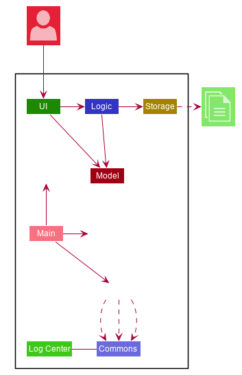
The Architecture Diagram given above explains the high-level design of the App. Given below is a quick overview of each component.
The .puml files used to create diagrams in this document can be found in the diagrams folder.
Refer to the Using PlantUML guide to learn how to create and edit diagrams.
|
-
At app launch: Initializes the components in the correct sequence, and connects them up with each other.
-
At shut down: Shuts down the components and invokes cleanup method where necessary.
Commons represents a collection of classes used by multiple other components.
The following class plays an important role at the architecture level:
-
LogsCenter: Used by many classes to write log messages to the App’s log file.
The rest of the App consists of four components.
Each of the four components
-
Defines its API in an
interfacewith the same name as the Component. -
Exposes its functionality using a
{Component Name}Managerclass.
For example, the Logic component (see the class diagram given below) defines it’s API in the Logic.java interface and exposes its functionality using the LogicManager.java class.
How the architecture components interact with each other
The Sequence Diagram below shows how the components interact with each other for the scenario where the user issues the command delete 1.
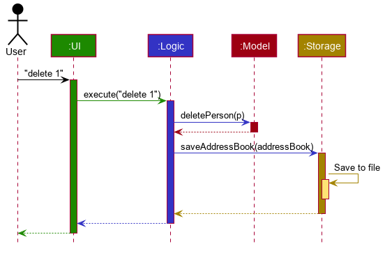
delete 1 commandThe sections below give more details of each component.
2.2. UI component
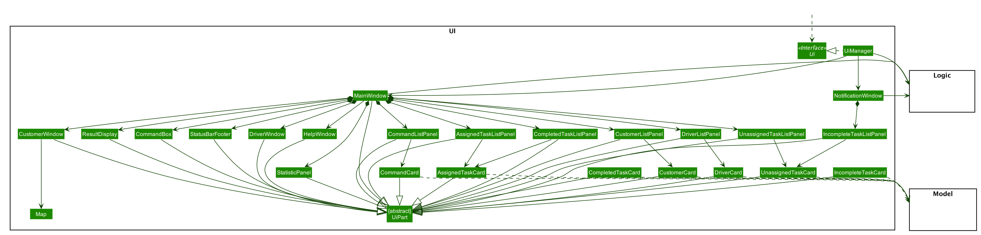
API : Ui.java
The UI consists of a MainWindow that is made up of parts e.g.CommandBox, ResultDisplay, DriverListPanel, StatusBarFooter etc. All these, including the MainWindow, inherit from the abstract UiPart class.
The UI component uses JavaFx UI framework.
The layout of these UI parts are defined in matching .fxml files that are in the src/main/resources/view folder.
For example, the layout of the MainWindow is specified in MainWindow.fxml
The UI component,
-
Executes user commands using the
Logiccomponent. -
Listens for changes to
Modeldata so that the UI can be updated with the modified data.
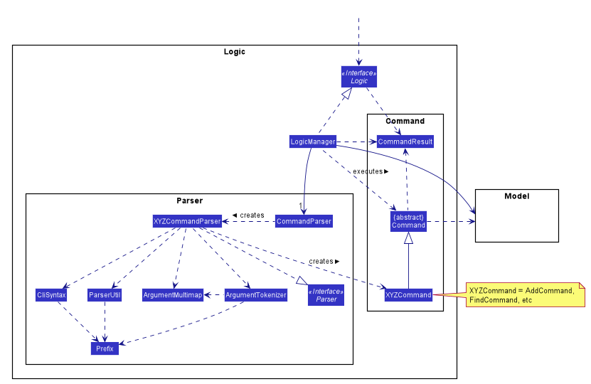
2.3. Logic component
API :
Logic.java
-
Logicuses theAddressBookParserclass to parse the user command. -
This results in a
Commandobject which is executed by theLogicManager. -
The command execution can affect the
Model(e.g. adding a person). -
The result of the command execution is encapsulated as a
CommandResultobject which is passed back to theUi. -
In addition, the
CommandResultobject can also instruct theUito perform certain actions, such as displaying help to the user.
Given below is the Sequence Diagram for interactions within the Logic component for the execute("del t/1") API call.
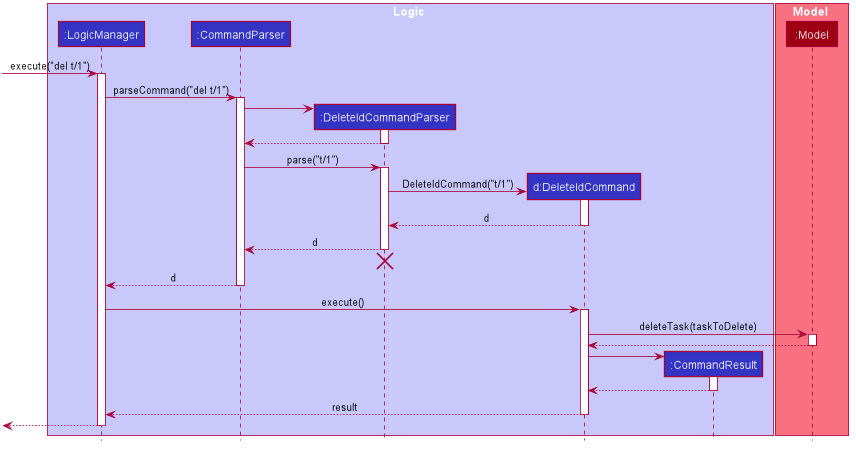
del t/1 Command
The lifeline for DeleteIdCommandParser should end at the destroy marker (X) but due to a limitation of PlantUML, the lifeline reaches the end of diagram.
|
2.4. Model component
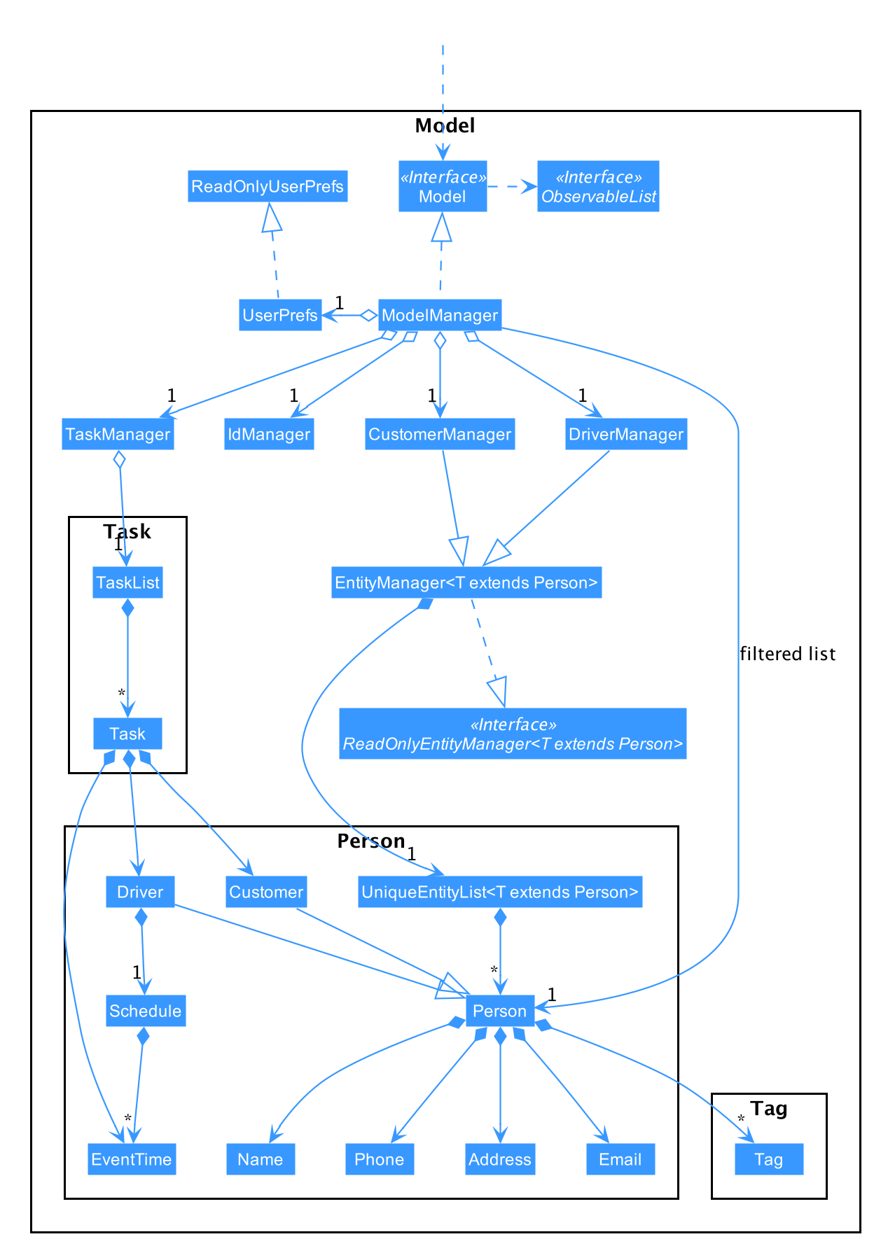
API : Model.java
The Model,
-
stores a
UserPrefobject that represents the user’s preferences. -
stores the
DriverManager,TaskManager,CustomerManagerandIdManager -
exposes unmodifiable
ObservableListthat can be 'observed' e.g. the UI can be bound to this list so that the UI automatically updates when the data in the list change. -
does not depend on any of the other three components.
2.5. Storage component
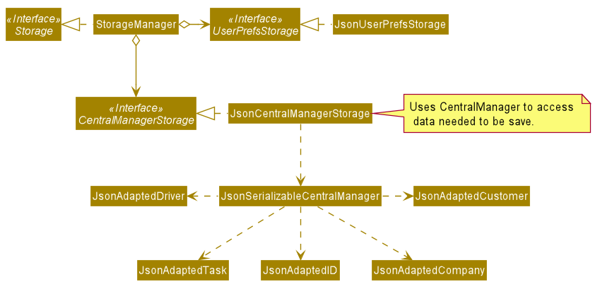
API : Storage.java
The Storage component,
-
can save
UserPrefobjects in json format and read it back. -
uses
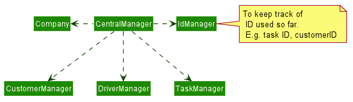
CentralManagerto consolidate all the data that needs to be saved. (e.g. Task Manager’s data) -
can save the
CentralManagerdata in json format and read it back. === Common classes
Classes used by multiple components are in the seedu.addressbook.commons package.
3. Implementation
This section describes some noteworthy details on how certain features are implemented.
3.1. Driver-Level Task Scheduling
3.1.1. Design Considerations
-
A
Scheduleshould be a collection of non-overlappingEventTimeobject, and is always sorted -
Should be able to notify the user if a better time slot is available, while giving users the liberty to exercise their own judgments
3.1.2. Implementation
Every Driver keeps track of a Schedule class, which is backed by a naturally sorted, TreeSet of EventTime objects.
Before a new EventTime is added to the schedule, the method checks against the TreeSet of EventTime to ensure the addition will not result in overlapping EventTime in the schedule.
This operation works in logarithmic time thanks to the tree structure.
In order to better utilise a driver, we implement a method to suggest an earlier alternative time slot in a schedule. When adding a time to a schedule, this method will:
-
Calculate the duration of proposed
EventTime -
Perform a linear greedy search in the schedule, to find the first slot that can fit the duration
Since the schedule guarantees no overlapping EventTime, there is no complication in handling the start and end times.
|
In order to enforce the optimised scheduling method above, the program will block every assign command that has a suboptimal proposed time, unless the user uses the force argument.
Moreover, the assign and free command are the only commands that modify the Driver and EventTime attributes of a Task, so that all drivers will have an optimised schedule, unless force assign is used.
The following activity diagram summarizes the checks happened when user executes an assign command.
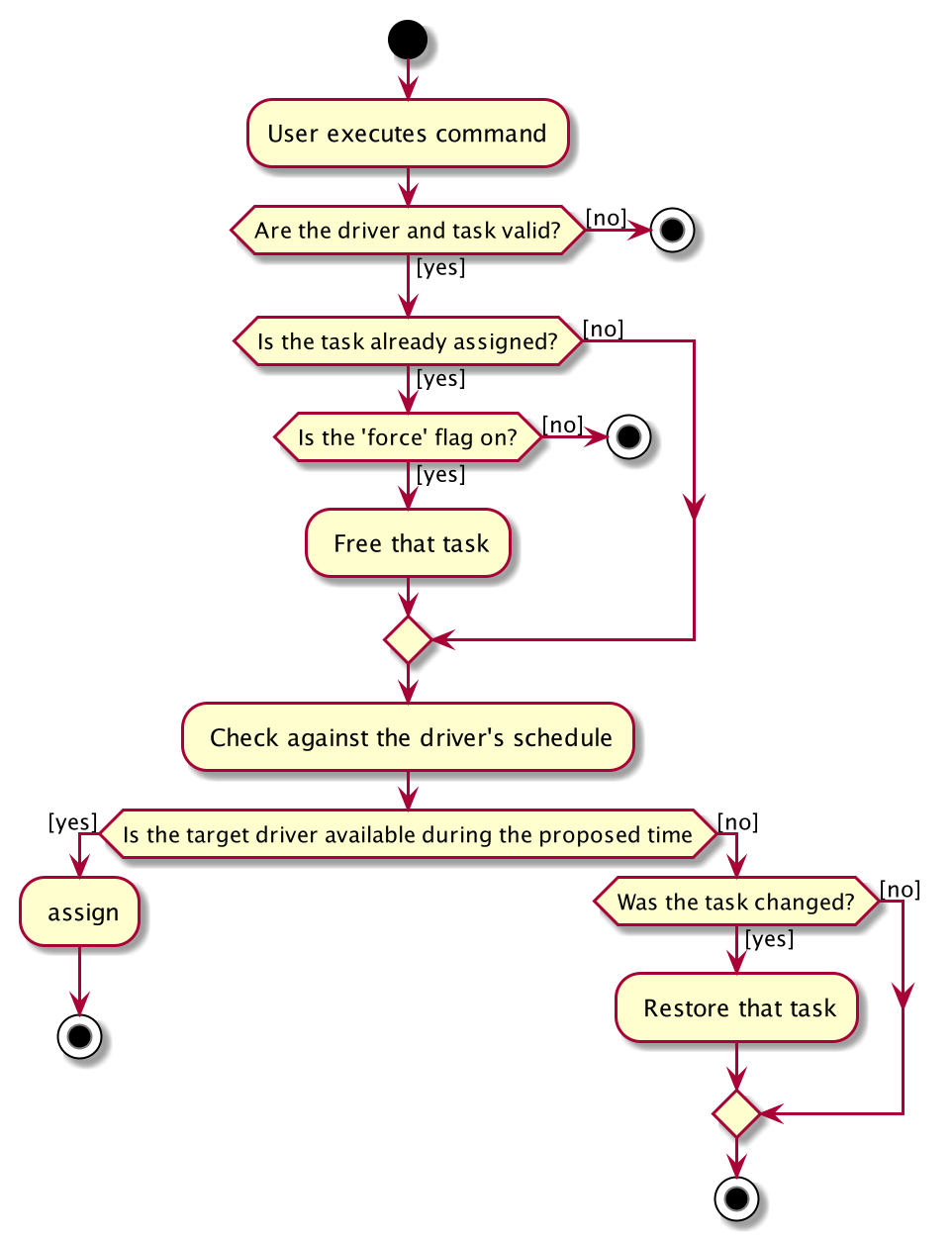
After the above checks has passed, assign command will:
-
Set the
DriverandEventTimeattributes in theTask -
Add the proposed
EventTimeto theDriver'sSchedule
Similarly, calling free command will:
-
Remove the existing
EventTimefrom theDriver'sSchedule -
Set the
DriverandEventTimeattributes tonull
3.2. Global-Level Task Scheduling
3.2.1. Design Considerations
-
The global-level scheduler needs to consider the task’s details (eg. the customer and address) and all the drivers' schedules, in order to optimize manpower allocation
-
The scheduler needs to be extendable, ie. easily incorporate new rules
3.2.2. Implementation
The ScheduleOptimizer class is a component in the Logic Layer, that have access to the entire model, in order to gather information about all drivers and tasks.
The object instantiates with Model and Task, and is designed to be discarded after use.
It will return a Candidate object, which is a wrapper class of javafx.util.Pair<Driver,Optional<EventTime>>.
This can be used by the caller to assign the task to the suggested driver at the suggested time.
It exposes a convenient ScheduleOptimizer#start method, to start optimizing, based on the rules implement in the Optimizer.
The start method uses a functional pipeline approach, by piping the Optional output of the rules.
It is implemented so that, the next stage of the pipeline will only be triggered when this stage of the pipeline fails to find a candidate (ie. returns an empty Optional).
The Optimizer consists of two rules as of now: ScheduleOptimizer#driverEarliestFit and ScheduleOptimizer#prioritizeSameCustomer.
Both methods are nullary functions that return a Optional<Candidate>.
Any new rule just need to follow the same method signature as the existing rules, and be added to the pipeline in the ScheduleOptimizer#start method.
3.3. Task Feature (E.g. Add Delivery Task)
3.3.1. Implementation
The Add Delivery Task feature adds a new task into a task list.
It uses the AddTaskCommand, which extends Command, to add a Task into the TaskManager.
AddTaskCommandParser is also utilised to parse and validate the user inputs before sending it to AddTaskCommand to execute.
'AddTaskCommand' requires the following fields: Task, customerId.
The attributes of Task is as follows:
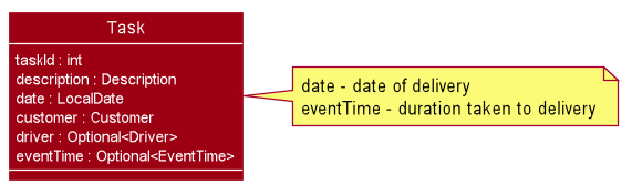
As seen in the above class diagram, driver and eventTime are optional fields that are not mandatory when adding a task.
They will be assigned subsequently using assign command.
(Refer to Assign feature) The mandatory fields for users are: 'description', 'date' and 'Customer'.
After the validation is completed, AddTaskCommand will fetch Customer using the customerId through the CustomerManager.
A unique id will also be allocated to the task for differentiation.
The following sequence diagrams show how the add task operation works:
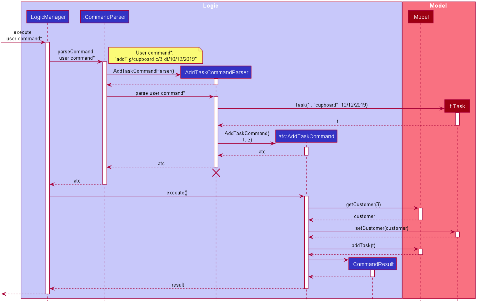
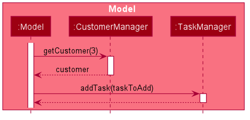
The flow of how the task is being accessed and managed as shown above is the same for other task related command such as edit task command (editT) and delete task command (del).
|
3.3.2. Design Considerations
Aspect: Coupling of Task and other entities (Driver and Customer)
-
Alternative 1 (current choice): Task class contains Driver and Customer classes as attributes.
-
Pros: Centralised Task class that encapsulates all the information, which makes it easy to manage task.
-
Cons: Task will have to depend on Driver and Customer. Decreases testability.
-
-
Alternative 2: Driver and Customer classes have Task class as attribute.
-
Pros: Easy to access tasks through the respective classes. (Driver and Customer classes)
-
Cons: Having 2 classes depend on Task class. Decreases testability.
-
3.4. Generate Task Summary and Delivery Orders in PDF Feature
3.4.1. Implementation
Generation of PDF documents is handled by PdfManager.
It is responsible in taking the essential inputs required to generate the document.
The following inputs are required to generate a PDF document such as a PDF Delivery Order:
-
filePath- the directory where the pdf document is to be saved. -
data- the data that is to be displayed in the PDF document.
The PdfManager utilizes PdfCreator to create and save the PDF document as well as formatting the layouts.
It is implemented with the help of an external library, iText7.
|
Regarding iText’s license, it can be used for free in situations where you distribute your software for free.
It is a Affero General Public License (AGPL) library. Information updated as of 6 November 2019. For more information, please visit the iText official website. |
To show how the PDF document is generated, generating PDF Task Summary will be used as an example for this showcase.
The following sequence diagram shows how the user command savepdf is being executed and handled.
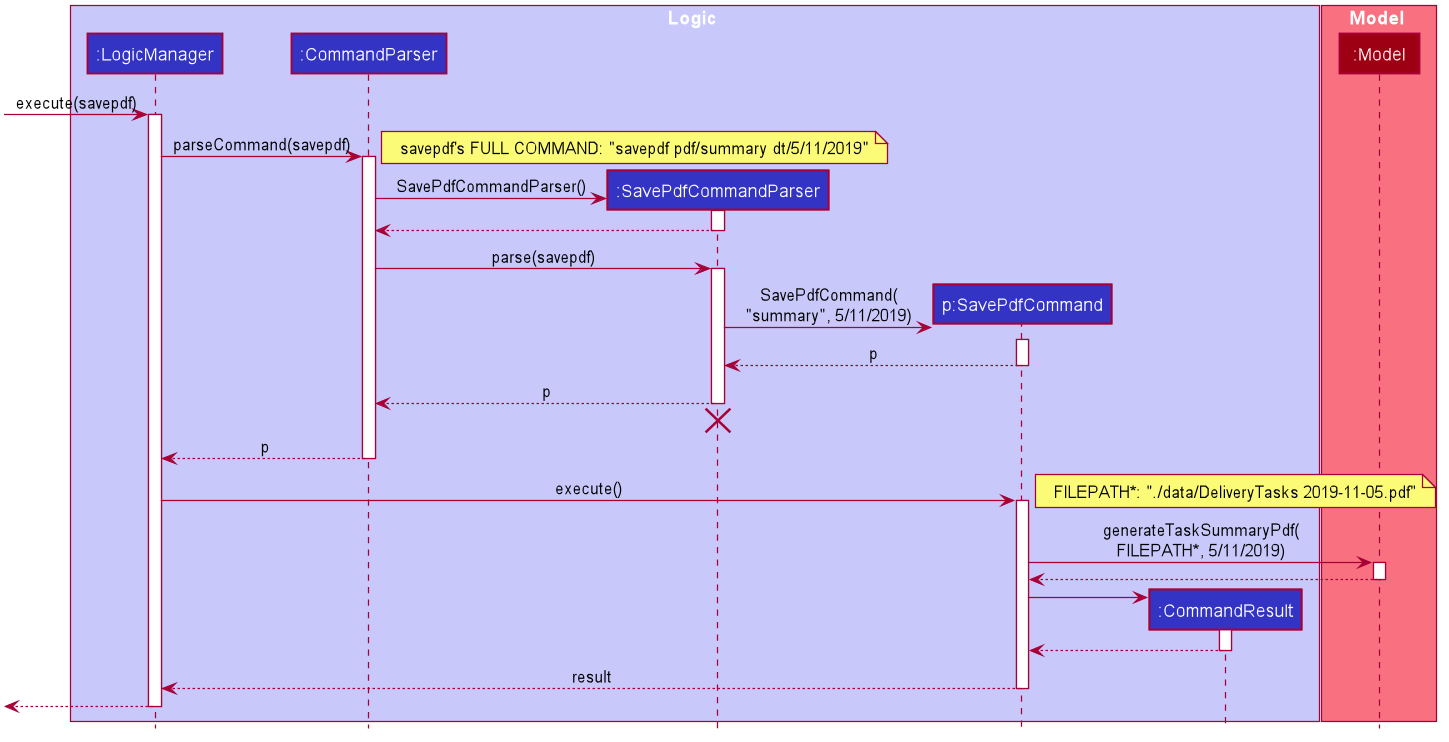
The lifeline for SavePdfCommandParser should end at the destroy marker (X) but due to a limitation of PlantUML, the lifeline reaches the end of diagram.
|
Notice that only the filepath and the date of delivery is needed when calling generateTaskSummaryPdf.
This is because only the saving location of the PDF file and the date, where the task summary will be based on, are the only fields needed for the PdfManager.
The rest of the components, such as fetching of the tasks, will be handled in the Model while the formatting will be handled by PdfCreator.
The following sequence diagram shows how the model interact with PdfManager to generate the PDF task summary.
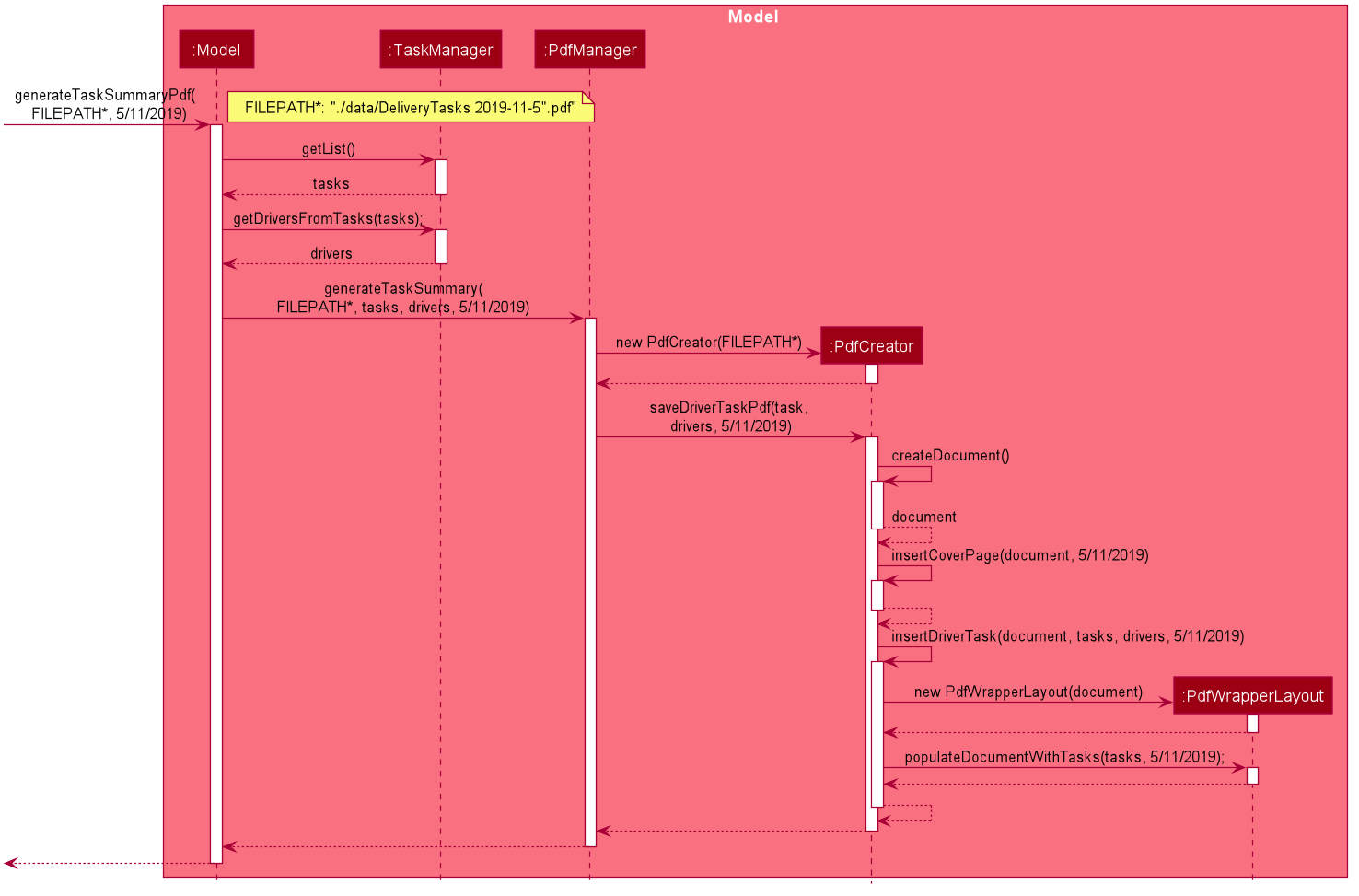
PdfManager to generates the PDF task summary.The PdfWrapperLayout provides a outer canvas to encapsulates all the layouts.
The following layouts are mainly what makes up the task summary:
-
PdfDriverLayoutclass - wraps driver details. -
PdfCustomerLayoutclass - wraps customer details. -
PdfTaskLayoutclass - wraps task details.
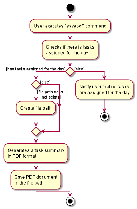
The following activity diagram shows what happens when a user executes the savepdf command:
3.4.2. Design Considerations
Aspect:
-
Alternative 1 (current choice): Abstract the layout of each part of the PDF document (Eg. Class that handles task layout is separated from class that handles customer layout.)
-
Pros: Encourages reuse and easier to manage and add on.
-
Cons: Harder to implement.
-
-
Alternative 2: Do the whole PDF document layout in 1 class.
-
Pros: Easy to implement.
-
Cons: Harder to manage.
-
3.5. [Proposed] View completed Task delivered for customer or driver
The section allows the user to view the completed tasks by driver or customer The following activity diagram summarizes what happens when a user executes a new command:
viewC 10

The following is the sequence diagram summarizes what happens when a user executes a new command:
viewC 1

viewC 2
3.6. [Proposed] Undo/Redo feature
3.6.1. Proposed Implementation
The undo/redo mechanism is facilitated by VersionedAddressBook.
It extends AddressBook with an undo/redo history, stored internally as an addressBookStateList and currentStatePointer.
Additionally, it implements the following operations:
-
VersionedAddressBook#commit()— Saves the current address book state in its history. -
VersionedAddressBook#undo()— Restores the previous address book state from its history. -
VersionedAddressBook#redo()— Restores a previously undone address book state from its history.
These operations are exposed in the Model interface as Model#commitAddressBook(), Model#undoAddressBook() and Model#redoAddressBook() respectively.
Given below is an example usage scenario and how the undo/redo mechanism behaves at each step.
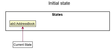
Step 1. The user launches the application for the first time.
The VersionedAddressBook will be initialized with the initial address book state, and the currentStatePointer pointing to that single address book state.
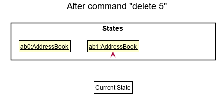
Step 2. The user executes delete 5 command to delete the 5th person in the address book.
The delete command calls Model#commitAddressBook(), causing the modified state of the address book after the delete 5 command executes to be saved in the addressBookStateList, and the currentStatePointer is shifted to the newly inserted address book state.
Step 3. The user executes add n/David … to add a new person.
The add command also calls Model#commitAddressBook(), causing another modified address book state to be saved into the addressBookStateList.
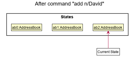
If a command fails its execution, it will not call Model#commitAddressBook(), so the address book state will not be saved into the addressBookStateList.
|
Step 4. The user now decides that adding the person was a mistake, and decides to undo that action by executing the undo command.
The undo command will call Model#undoAddressBook(), which will shift the currentStatePointer once to the left, pointing it to the previous address book state, and restores the address book to that state.
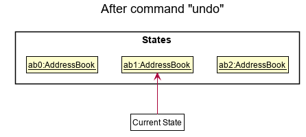
If the currentStatePointer is at index 0, pointing to the initial address book state, then there are no previous address book states to restore.
The undo command uses Model#canUndoAddressBook() to check if this is the case.
If so, it will return an error to the user rather than attempting to perform the undo.
|
The following sequence diagram shows how the undo operation works:
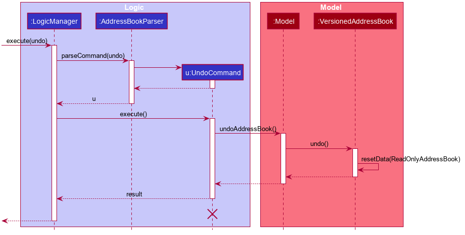
The lifeline for UndoCommand should end at the destroy marker (X) but due to a limitation of PlantUML, the lifeline reaches the end of diagram.
|
The redo command does the opposite — it calls Model#redoAddressBook(), which shifts the currentStatePointer once to the right, pointing to the previously undone state, and restores the address book to that state.
If the currentStatePointer is at index addressBookStateList.size() - 1, pointing to the latest address book state, then there are no undone address book states to restore.
The redo command uses Model#canRedoAddressBook() to check if this is the case.
If so, it will return an error to the user rather than attempting to perform the redo.
|
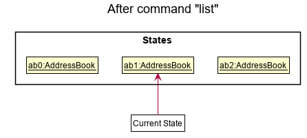
Step 5. The user then decides to execute the command list.
Commands that do not modify the address book, such as list, will usually not call Model#commitAddressBook(), Model#undoAddressBook() or Model#redoAddressBook().
Thus, the addressBookStateList remains unchanged.
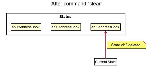
Step 6. The user executes clear, which calls Model#commitAddressBook().
Since the currentStatePointer is not pointing at the end of the addressBookStateList, all address book states after the currentStatePointer will be purged.
We designed it this way because it no longer makes sense to redo the add n/David … command.
This is the behavior that most modern desktop applications follow.
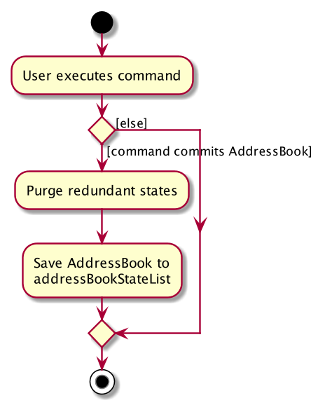
The following activity diagram summarizes what happens when a user executes a new command:
3.6.2. Design Considerations
Aspect: How undo & redo executes
-
Alternative 1 (current choice): Saves the entire address book.
-
Pros: Easy to implement.
-
Cons: May have performance issues in terms of memory usage.
-
-
Alternative 2: Individual command knows how to undo/redo by itself.
-
Pros: Will use less memory (e.g. for
delete, just save the person being deleted). -
Cons: We must ensure that the implementation of each individual command are correct.
-
Aspect: Data structure to support the undo/redo commands
-
Alternative 1 (current choice): Use a list to store the history of address book states.
-
Pros: Easy for new Computer Science student undergraduates to understand, who are likely to be the new incoming developers of our project.
-
Cons: Logic is duplicated twice. For example, when a new command is executed, we must remember to update both
HistoryManagerandVersionedAddressBook.
-
-
Alternative 2: Use
HistoryManagerfor undo/redo-
Pros: We do not need to maintain a separate list, and just reuse what is already in the codebase.
-
Cons: Requires dealing with commands that have already been undone: We must remember to skip these commands. Violates Single Responsibility Principle and Separation of Concerns as
HistoryManagernow needs to do two different things.
-
3.7. Logging
We are using java.util.logging package for logging.
The LogsCenter class is used to manage the logging levels and logging destinations.
-
The logging level can be controlled using the
logLevelsetting in the configuration file (See Section 3.8, “Configuration”) -
The
Loggerfor a class can be obtained usingLogsCenter.getLogger(Class)which will log messages according to the specified logging level -
Currently log messages are output through:
Consoleand to a.logfile.
Logging Levels
-
SEVERE: Critical problem detected which may possibly cause the termination of the application -
WARNING: Can continue, but with caution -
INFO: Information showing the noteworthy actions by the App -
FINE: Details that is not usually noteworthy but may be useful in debugging e.g. print the actual list instead of just its size
3.8. Configuration
Certain properties of the application can be controlled (e.g user prefs file location, logging level) through the configuration file (default: config.json).
3.9. Customer Feature
3.9.1. Add Customer
Implementation
The Add Customer feature adds a new Customer into a Customer list.
It uses the AddCustomerCommand, which extends Command, to add a Customer into the CustomerManager.
AddCustomerCommandParser is also utilised to parse and validate the user inputs before sending it to AddCustomerCommand to execute.
AddCustomerCommand requires the following fields: Customer.
The attributes of Task is as follows:
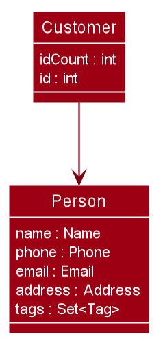
As seen in the above class diagram, the id field is not required when adding a customer.
The mandatory fields for users are: name, phone, email, address.
A unique id will also be allocated to the Customer for differentiation.
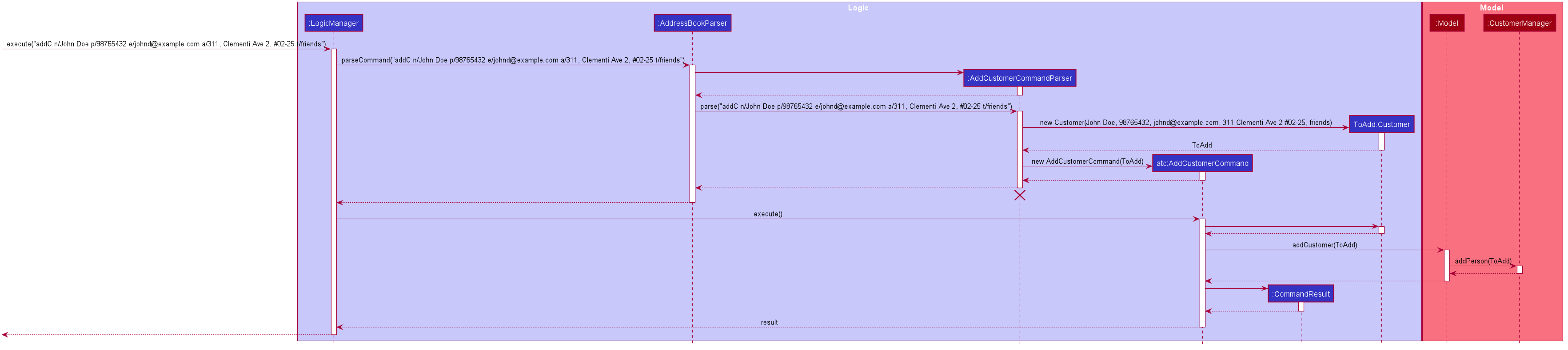
The following sequence diagram shows how the add customer operation works:
Design Considerations
Aspect: Usage of universal Command word
-
Alternative 1 (current choice): Have a individual command word for adding customer. (
addC)-
Pros: Easy to implement and increases clarity for users.
-
Cons: Increases the number of commands.
-
-
Alternative 2: Combine
AddCustomerCommandwith otheraddcommands-
Pros: Will use only 1 universal
addcommand for adding any entities. (Task, Customer and Driver) -
Cons: Have to handle different type of parameters and some parameters of commands are overlap which requires more validation.
-
3.9.2. View Customer Window
Implementation
The View Customer Window retrieves the details of a Customer and displays it in a separate window.
It uses the ViewCustomerWindowCommand, which extends Command, to return a CommandResult with a boolean value viewCustomer as true.
ViewCustomerWindowCommandParser is also utilised to parse and validate the user inputs before sending it to ViewCustomerWindowCommand to execute.
ViewCustomerWindowCommand requires the following fields:`customerId`.
| A working internet connection and a valid address is needed for the map to show in the window. |
The following sequence diagram shows how the user command viewCW is being executed and handled.
Aspect:
-
Alternative 1 (current choice): Show full details of customer in separate window.
-
Pros: Unnecessary details of driver clutters up the UI. This cleans up the UI allowing the card to only show all essential details. Allow the space for working map showing the location of the customer’s address.
-
Cons: Harder to implement.
-
-
Alternative 2: Show full details of driver in a single card in main window.
-
Pros: Easier to implement.
-
Cons: Cards becomes too big when schedule information gets too long. Ui looks very cluttered. Unable to show the map of customer’s address.
-
3.10. Driver Feature
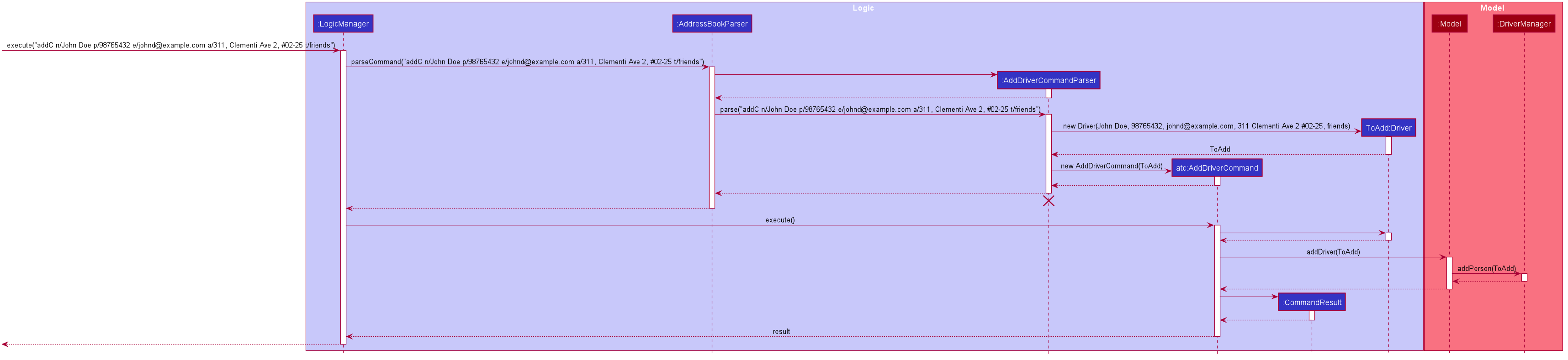
3.10.1. Add Driver
Implementation
The Add Driver feature adds a new Driver into a Driver list.
It uses the AddDriverCommand, which extends Command, to add a Driver into the DriverManager.
AddDriverCommandParser is also utilised to parse and validate the user inputs before sending it to AddCustomerCommand to execute.
AddDriverCommand requires the following fields: Driver.
The attributes of Driver is as follows:
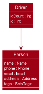
As seen in the above class diagram, the id field is not required when adding a driver.
The mandatory fields for users are: name, phone, email, address.
A unique id will also be allocated to the Driver for differentiation.
The following sequence diagram shows how the add driver operation works:
Design Considerations
Aspect: Usage of universal Command word
-
Alternative 1 (current choice): Have a individual command word for adding driver. (
addD)-
Pros: Easy to implement and increases clarity for users.
-
Cons: Increases the number of commands.
-
-
Alternative 2: Combine
AddDriverCommandwith otheraddcommands-
Pros: Will use only 1 universal
addcommand for adding any entities. (Task, Customer and Driver) -
Cons: Have to handle different type of parameters and some parameters of commands are overlap which requires more validation.
-
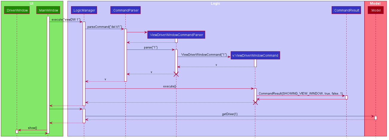
3.10.2. View Driver Window
Implementation
The View Driver Window retrieves the details of a Driver and displays it in a separate window.
It uses the ViewDriverWindowCommand, which extends Command, to return a CommandResult with a boolean value viewDriver as true.
ViewDriverWindowCommandParser is also utilised to parse and validate the user inputs before sending it to ViewDriverWindowCommand to execute.
ViewDriverWindowCommand requires the following fields:`driverId`.
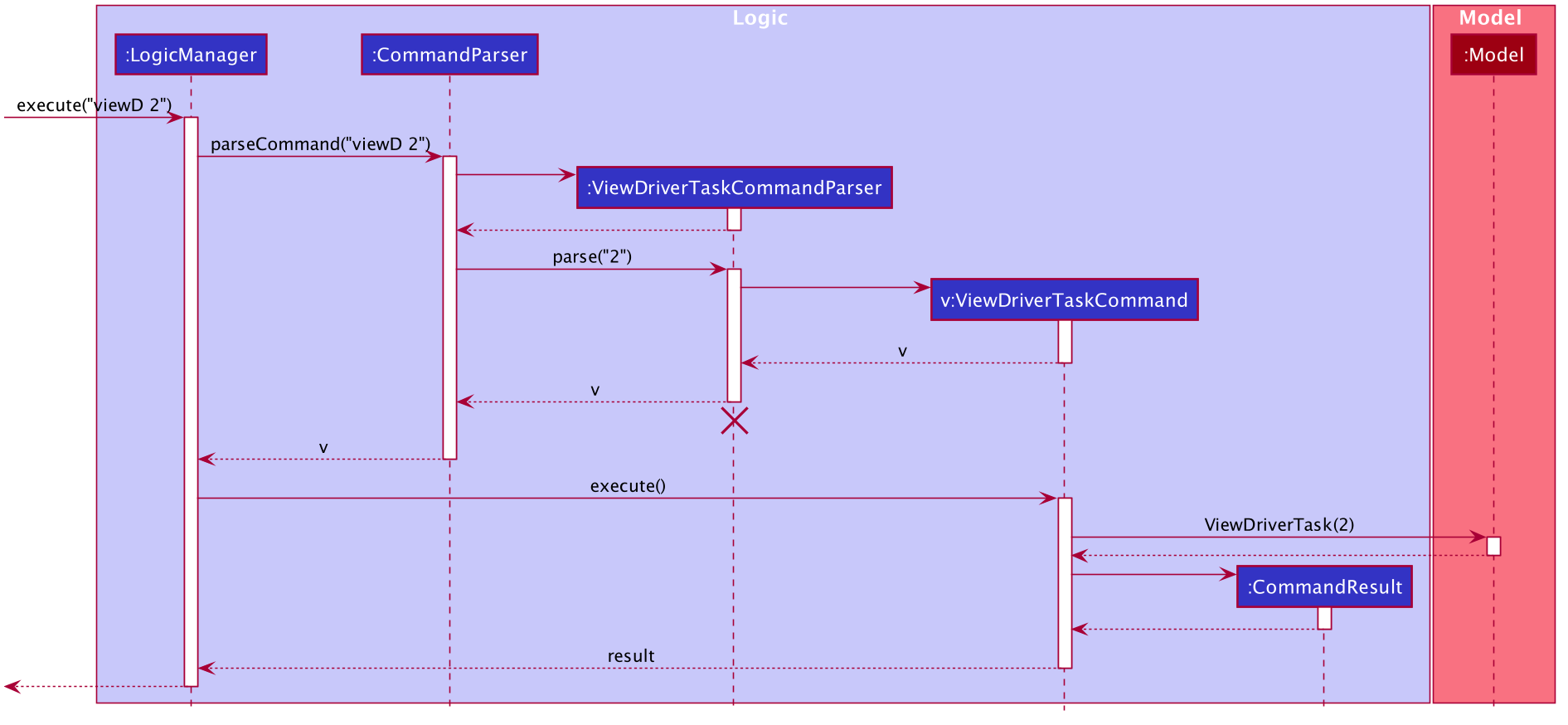
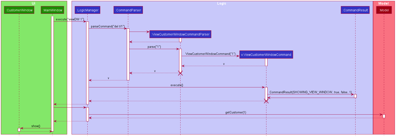
The following sequence diagram shows how the user command viewDW is being executed and handled.
Aspect:
-
Alternative 1 (current choice): Show full details of driver in separate window.
-
Pros: Unnecessary details of driver clutters up the UI. This cleans up the UI allowing the card to only show all essential details.
-
Cons: Harder to implement.
-
-
Alternative 2: Show full details of driver in a single card in main window.
-
Pros: Easier to implement.
-
Cons: Cards becomes too big when schedule information gets too long. Ui looks very cluttered.
-
4. Documentation
Refer to the guide here.
5. Testing
Refer to the guide here.
6. Dev Ops
Refer to the guide here.
Appendix A: Product Scope
Target user profile:
-
has a need to manage a significant number of delivery tasks and drivers
-
prefer desktop apps over other types
-
can type fast
-
prefers typing over mouse input
-
is reasonably comfortable using CLI apps
Value proposition: manage delivery tasks faster than a typical mouse/GUI driven app
Appendix B: User Stories
Priorities: High (must have) - * * *, Medium (nice to have) - * *, Low (unlikely to have) - *
| Priority | As a … | I want to … | So that I can… |
|---|---|---|---|
|
Delivery manager |
view all unfinished delivery tasks |
know which tasks have yet to be delivered |
|
Delivery manager |
view all delivered tasks |
keep track of all delivered tasks in the past month |
|
Delivery manager |
sort and display delivery tasks by their starting time |
view pending tasks in an orderly manner |
|
Delivery Manager |
search for tasks by a keyword |
find a task more easily |
|
Delivery Manager |
toggle dark or light theme for the interface |
the UI can change according to user preference |
|
Delivery Manager |
see the image of the drivers |
can identify them easily |
{More to be added}
Appendix C: Use Cases
(For all use cases below, the System is the Deliveria and the Actor is the Delivery Manager, unless specified otherwise)
Use case: Delete Driver
MSS
-
Delivery Manager requests the list of drivers
-
Deliveria shows a list of drivers
-
Delivery Manager requests to delete a specific driver in the list
-
Deliveria deletes the driver
Use case ends.
Extensions
-
2a. The list is empty.
Use case ends.
-
3a. The given index is invalid.
-
3a1. Deliveria shows an error message.
Use case resumes at step 2.
-
Use case: Creating a new task
MSS
-
User creates a delivery task
-
Deliveria adds the task to a list of delivery tasks
-
Deliveria prints to assure that the task is added
Use case ends.
Extensions
-
1a. Task given in invalid format
-
1a1. Deliveria shows an error message
-
1a2. Use case resumes at step 1
Use case ends
-
Use Case: Assign Driver to delivery task
MSS
-
Delivery Manager view the incomplete task list.
-
Deliveria shows the incomplete task list.
-
User assign a driver to one of the task
-
Deliveria shows the confirmation of driver being assigned to the task.
-
Deliveria indicate the incomplete task as On-going.
Use case ends.
Extension
-
3a. If driver is unavailable to take up the task
-
3a1. Deliveria prompts that driver is busy
-
3a2. Deliveria shows the available time of the driver
Use case resumes at step 3.
-
{More to be added}
Appendix D: Non Functional Requirements
-
Should work on any mainstream OS as long as it has Java
11or above installed. -
Should be able to maintain up to 100 drivers and 1000 tasks without performance degradation.
-
A user with above average typing speed for regular English text (i.e. not code, not system admin commands) should be able to accomplish most of the tasks faster using commands than using the mouse.
-
Should comply with the company’s privacy regulations and safely store the data files.
-
Should be able to scale quickly and adaptable for different companies.
Appendix E: Glossary
- Mainstream OS
-
Windows 10, MacOS Mojave, Ubuntu
- Private contact detail
-
A contact detail that is not meant to be shared with others
Appendix F: Product Survey
Product Name
Author: …
Pros:
-
…
-
…
Cons:
-
…
-
…
Appendix G: Instructions for Manual Testing
Given below are instructions to test the app manually.
| These instructions only provide a starting point for testers to work on; testers are expected to do more exploratory testing. |
G.1. Launch and Shutdown
-
Initial launch
-
Download the jar file and copy into an empty folder
-
Double-click the jar file
Expected: Shows the GUI with a set of sample contacts. The window size may not be optimum.
-
-
Saving window preferences
-
Resize the window to an optimum size. Move the window to a different location. Close the window.
-
Re-launch the app by double-clicking the jar file.
Expected: The most recent window size and location is retained.
-
{ more test cases … }
G.2. Deleting a person
-
Deleting a person while all persons are listed
-
Prerequisites: List all persons using the
listcommand. Multiple persons in the list. -
Test case:
delete 1
Expected: First contact is deleted from the list. Details of the deleted contact shown in the status message. Timestamp in the status bar is updated. -
Test case:
delete 0
Expected: No person is deleted. Error details shown in the status message. Status bar remains the same. -
Other incorrect delete commands to try:
delete,delete x(where x is larger than the list size) {give more}
Expected: Similar to previous.
-
{ more test cases … }
G.3. Saving data
-
Dealing with missing/corrupted data files
-
{explain how to simulate a missing/corrupted file and the expected behavior}
-
{ more test cases … }